After last week's start of a new project, this week has been consumed with moving it along.
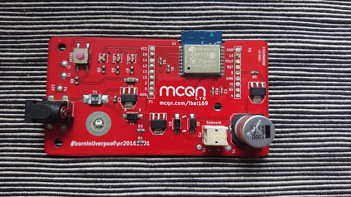
I got the basic circuit up and running pretty quickly, thanks in part to my general design-for-reuse approach in the past. The Bubblino and Ackers Bell PCB designs both have the main connections to the ESP8266 module broken out as standard-0.1"-pitch headers—the two vertiacl rows of 9 silver dots in the photo below. It adds a few millimetres to the size of the PCB but is otherwise a completely free addition in the production process, and then means the PCB can be repurposed for other uses.

There were a few iterations on the circuit across the week, as I refined things: breaking out an extra pin to allow use of the 4-pin Dotstar LEDs as well as the 3-pin Neopixels; switching the power supply for the ESP module from the 3.3V on the ATX connector to the 5V standby so the WLED software can turn the main power supply off when it's not in use...
As I went, I was laying the schematic out in Kicad. That's pretty much all done now, so next is turning that into the physical layout for the PCB.

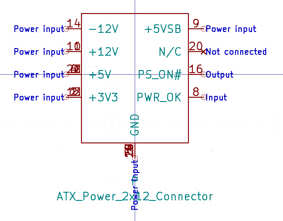
The Kicad library doesn't include the ATX power supply connector, so I needed to create that. While I was doing that, I wrote up the process as a tutorial for the Kicad course I'm running in December. A nice bit of doubling-up my output! I'll do the same for the connector footprint when I get to that.
And away from the technical work, I've made a start on some of the sales scaffolding. I had hoped to have a link to a product listing by now, but I need a couple more details to finalise that. I do now have a Tindie store, where the product listing will appear.

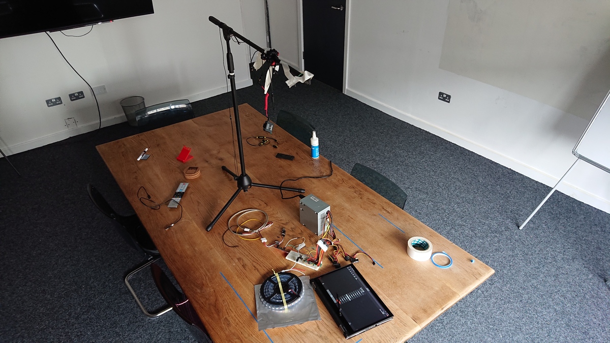
And I spent a bit of time doing some filming of the progress so far. That was my set up in one of the DoES Liverpool meeting rooms on Wednesday. A tiny bit of video editing later, I had this short demo video:
