Our last catch-up was all about one project: Museum in a Box; this one is about a couple of projects, but grouped on a single theme: bikes.
We're big fans of cycling in the studio, and within our wider community in Liverpool—this summer about twenty of us headed north to do the Ride to the Sun, a 100 mile overnight ride starting in Carlisle and ending on the coast in Edinburgh to watch the sun rise. Unsurprisingly, we've brought some of our electronics and fabrication skills to bear on bike-related activities.
My Bike's Got LED
My Bike's Got LED is the biggest of those projects. We did the first version of this board, which makes it easy to control RGB LED neopixels anywhere you've only got battery power, a couple of years back. That version worked but we've been making some improvements—mostly adding a charging circuit to the board.
We got as far as having some prototypes made of a revised version, but that stalled in testing; the charging circuit would charge the battery, but didn't ever decide to turn off the "we're still charging" status LED.
With the Museum in a Box redesign taking priority, this moved to a back-burner task to chip away at. In the background we came across a more promising charger chip, which also included a 5V boost circuit; that would let us reduce the number of components on the circuit, making it smaller and maybe a bit cheaper. We also decided that maybe we should make the move from an ESP8266 processor module to the newer ESP32, as that would let us add the option of having the lights react to sound or music. A much-requested feature from our Friday night group rides, given the soundsystem accompaniment.
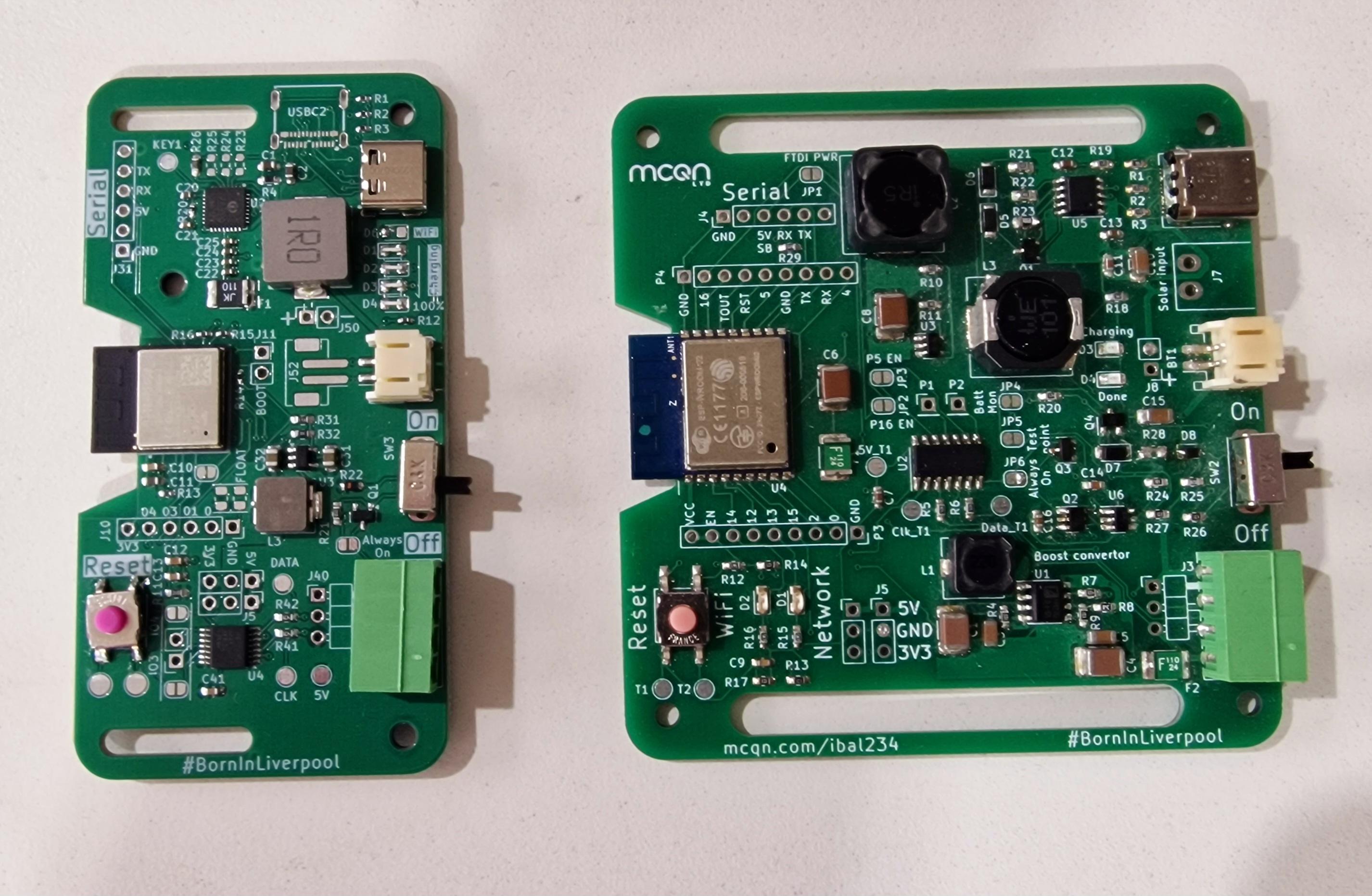
With the Museum in a Box hardware updated, Chris has had the opportunity to pick this back up. We spent a while going back and forth over charger choices, poring over datasheets and weighing up the options. We didn't go with our initial replacement chip, but still have one with an integrated 5V boost circuit. As you can see above, Chris has shrunken the footprint to almost half of the original version; more importantly, the charging circuit seems to be functioning correctly and indicates when it's done!
Like last time, we've had a few prototypes fabbed before a production run. So far the results of our testing are promising. There are a few things still to check through, and then we can get some made for sale.
Bike Head
The My Bike's Got LED boards are excellent, but a little high-end (price-wise at least) for kids bikes. For a while we've been pondering on that; wondering if the super-flexible LED "noodles" would be another way to add some colour, fun and light to bikes. Maybe we could also leverage the availability of the micro:bit boards in schools and the like.
Working out how to mount it all onto the bike was a conundrum, until Adrian spotted a craft project to make "heads" for bikes out of cardboard. That would let kids personalise and customise the design: decorating and modifying the cardboard; positioning the LEDs... and the micro:bit could be bolted to the back.
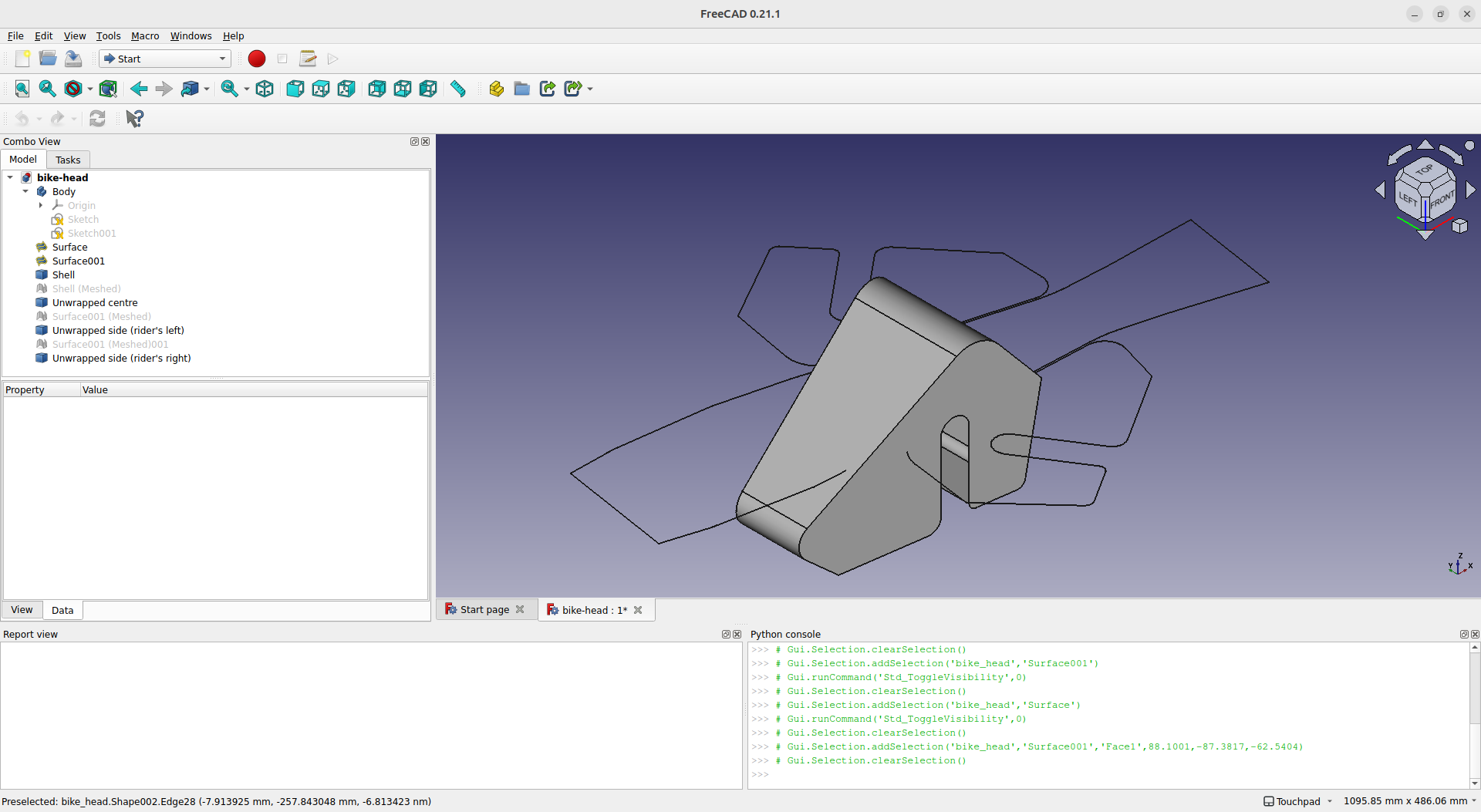
Designing a prototype let us expand our FreeCAD skills, learning about unwrapping meshes from a designed solid in order to flatten the three dimensional shape into something we could laser-cut.
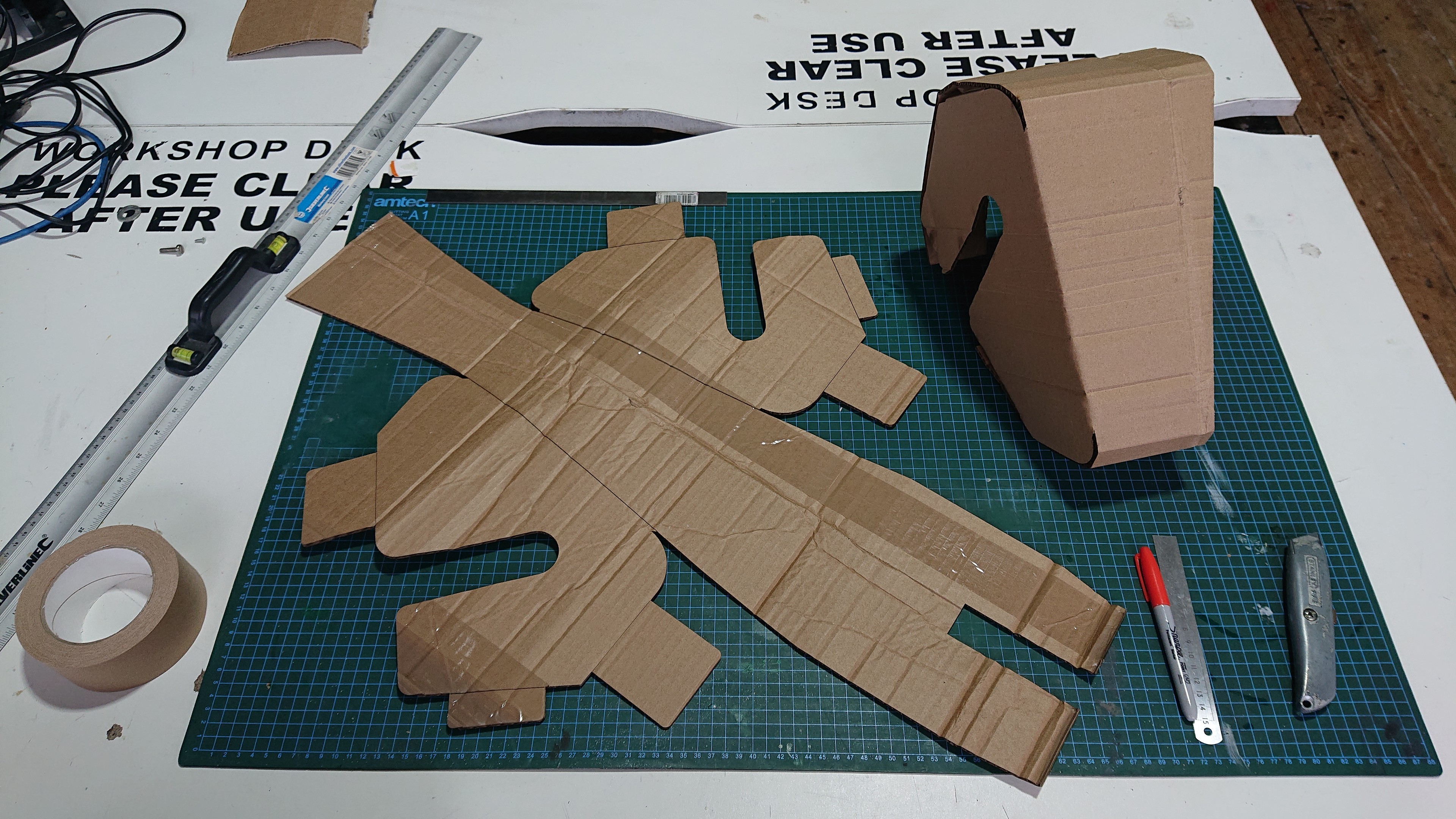
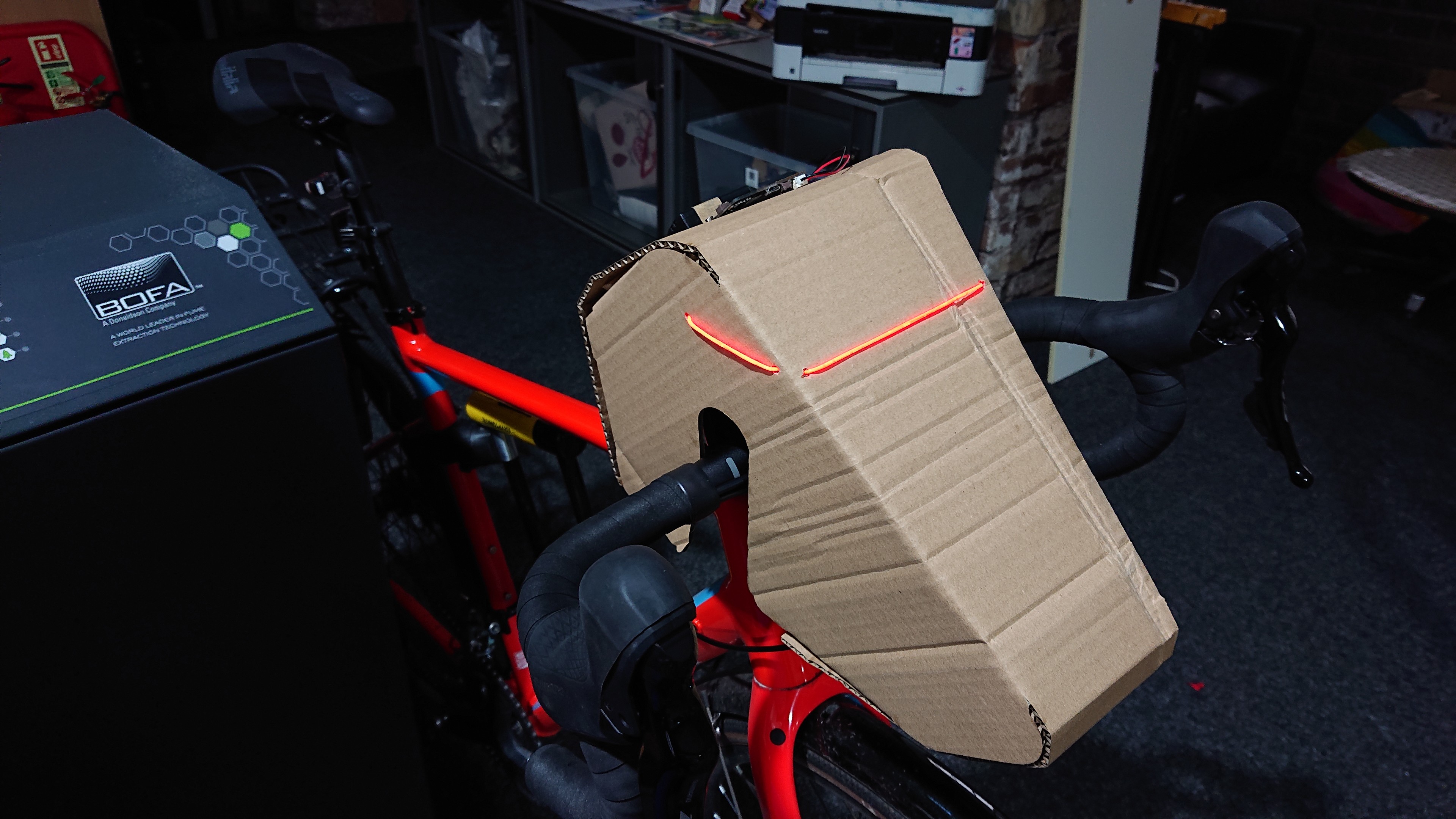
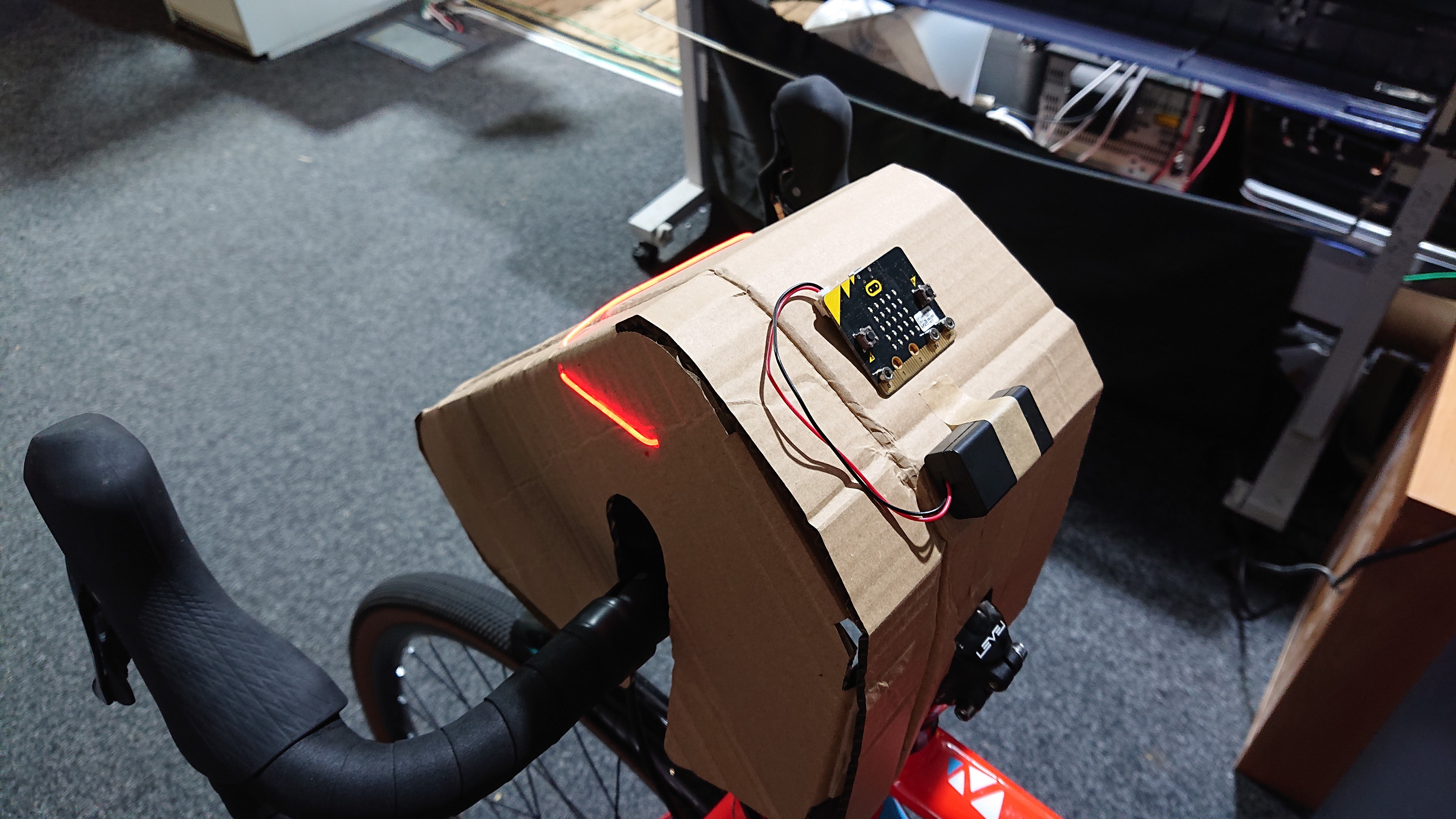
That worked nicely, although we need to test the Bike Heads on a wider variety of bikes to fine-tune the fitting. Adrian has designed a simple circuit-board to let the micro:bit control up to three LED noodles, and power it all off a pair of AA batteries; and we've had an initial batch of those made for some wider testing.
We've also been chatting to Peloton Liverpool bike co-op about how they can use these as part of their learn-to-ride sessions. The Bluetooth capability of the micro:bit boards is going to let us build some fun games with it!
Sound-system Sender
Speaking of fun, most Friday evenings a group of us get together for a social ride round the city. There'll be anything from half-a-dozen to forty-odd of us. We pick quieter routes so we can ride side-by-side for a chat as well as some exercise, and get all over the city (more on that later).
We also take some tunes with us and play them on a loudspeaker mounted to one of the bikes. Sometimes we'll do a special ride with performers on a trike.
As the group gets bigger, a single loudspeaker isn't enough to cover the whole ride. We realised we could re-purpose our Rode wireless microphone to act as a wireless relay to run a second speaker.
The Rode units have clips to hold them on clothing but they're not ideal for mounting on bikes. Adrian broke out FreeCAD and designed a sleeve for each end with a GoPro mount, so it would fit with the camera-mounts that he already had.
A couple of 3D prints later, and we could mount them to poles attached to the bikes. That let us get the wireless section up above the height of the riders, meaning their bodies and bikes wouldn't get in the way of the radio transmission.
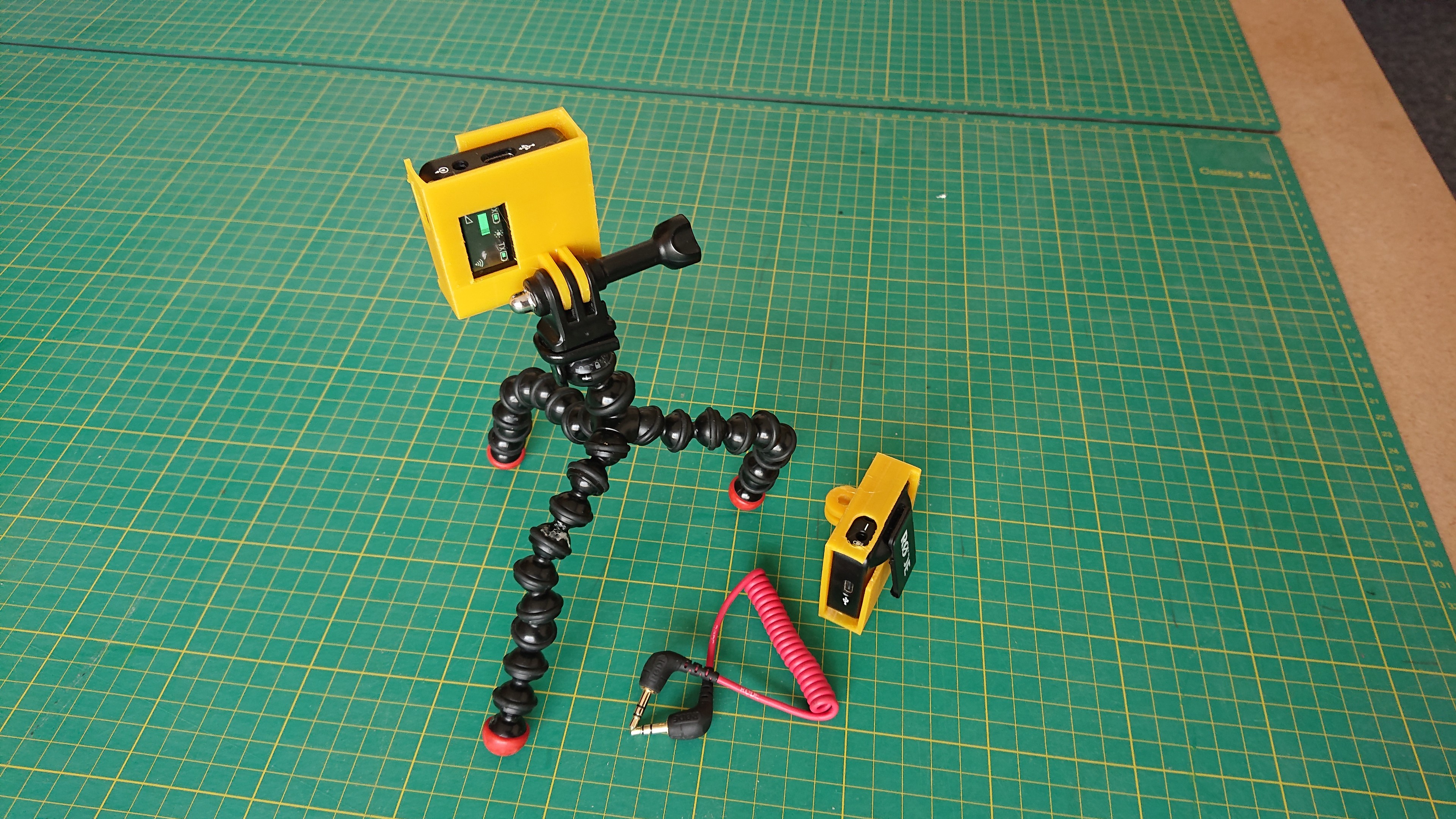
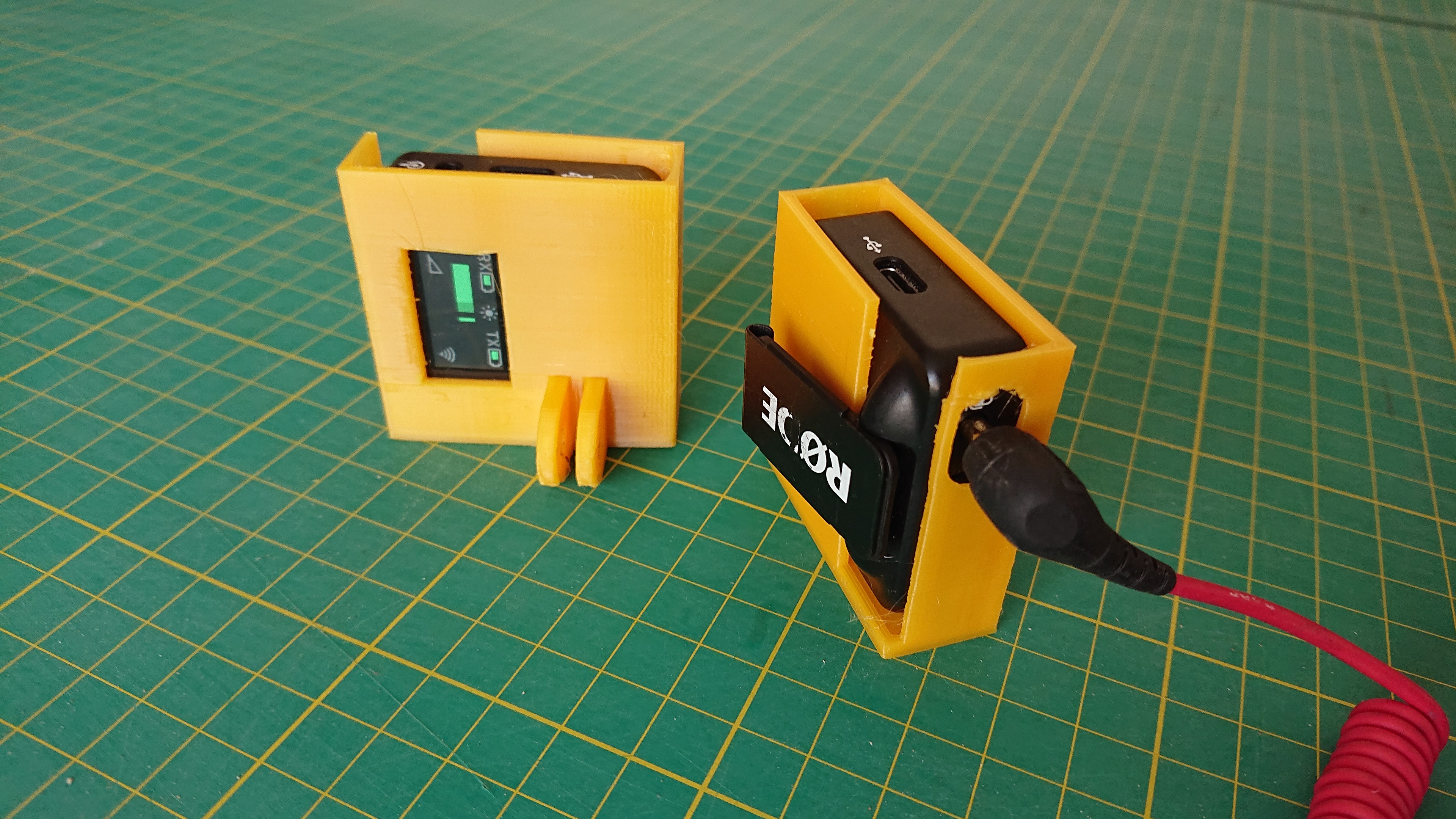
That covered the wireless side of things. The Rode mic has an input port to plug in a lapel mic and we were (ab)using that to connect the line-out from the source speaker. The line-out signal is already pre-amplified, which meant that it was getting further amplified by the mic unit and distorting the signal.
For its first outing Adrian knocked up a quick-and-dirty stereo attenuation circuit, which did the trick but wasn't exactly robust. KiCAD and FreeCAD made translating that into something suitable for the long-term pretty simple.
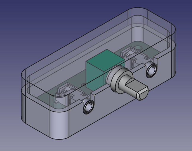
This was the design, ready to submit to the Open Source Hardware Association for certification. Not long afterwards we heard back that it's been certified as UK000066. Yay!
We then ended up getting a bumper order of boards fabbed: the My Bike's Got LED prototypes; a run of the Bike Head boards; and a couple of these audio level shifter PCBs. Once they turned up, we printed off the case and soldered one up.
Here you can see the transition from the initial quick-and-dirty test board to the finished item:
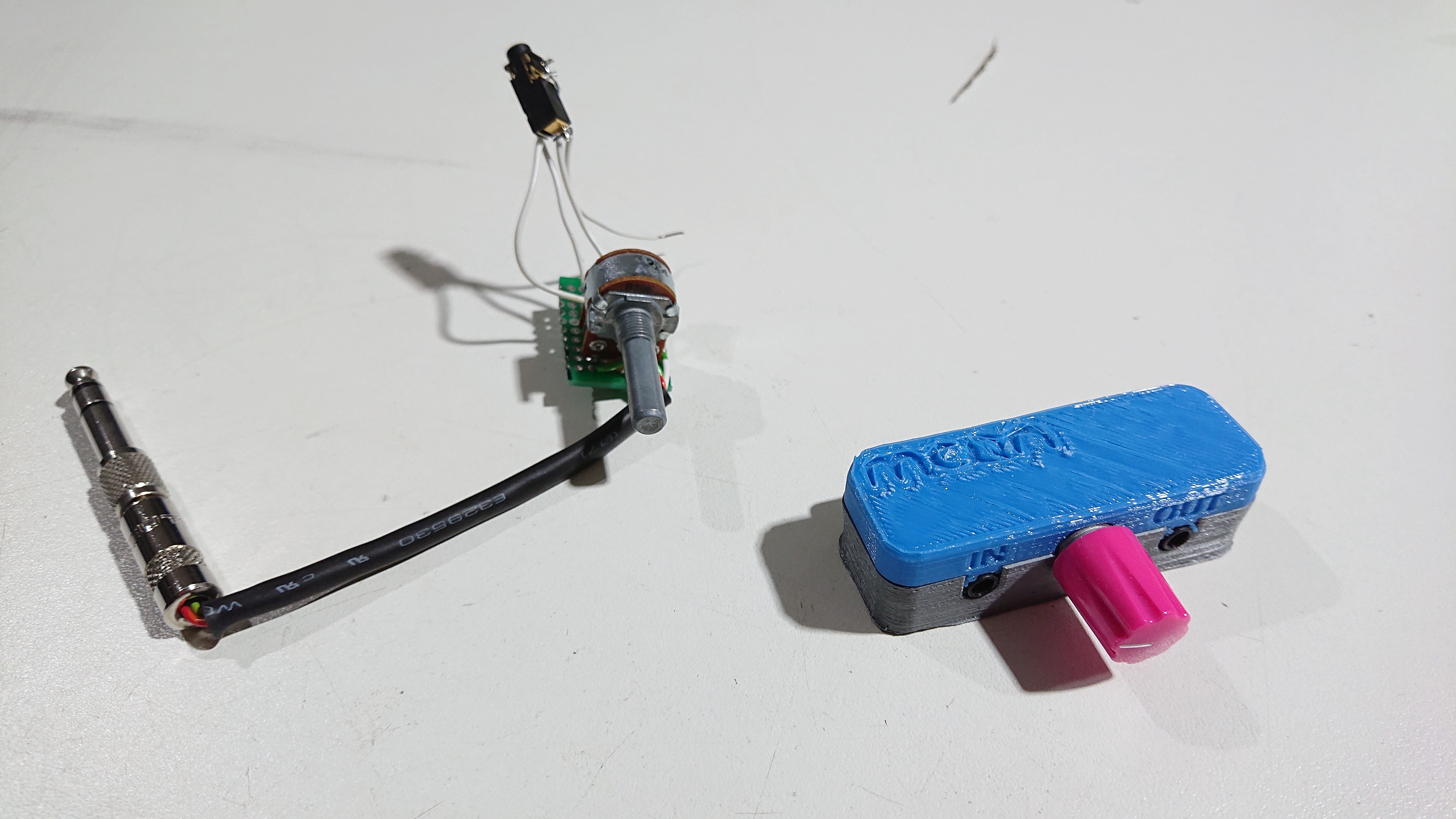
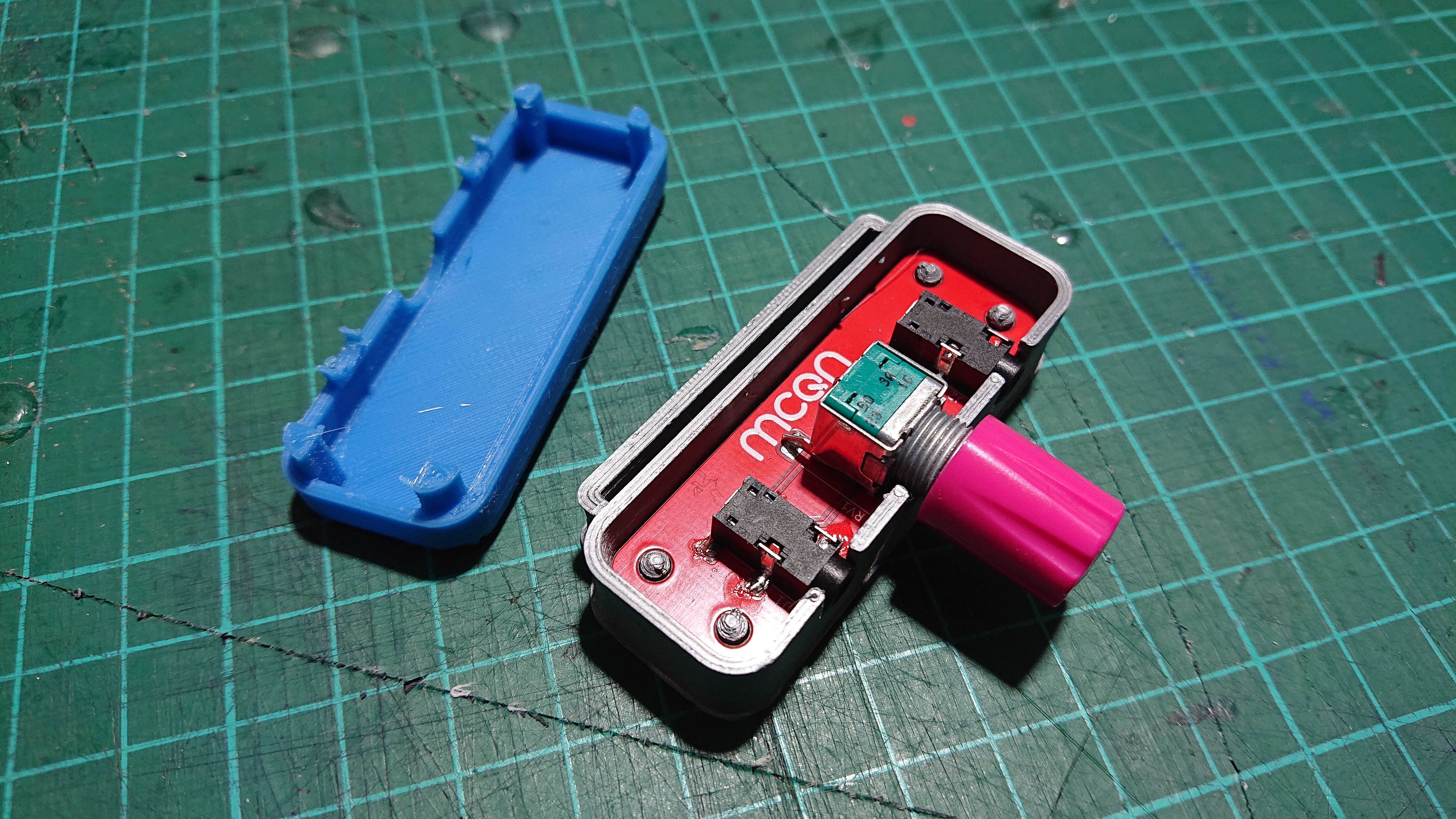
It was a nice exercise in design with open tools, released as open hardware. We're not expecting it to be super popular, so it won't be a product, but even internal projects get a catalogue number and the source files for the PCB, case and Rode GoPro mounts are all available for anyone else to use.
If you want to see it in action you can just make out the transmitter mounted atop the pole on the bike here, and the receiver was mounted just below the camera on the following bike.
Joy Riding
The #JoyRide group rides have been running for a few years now, and in that time have explored all across Liverpool and its environs. Adrian has been collecting the new routes with his phone and adding them to an online map but thought it would be nice to turn that into a poster.
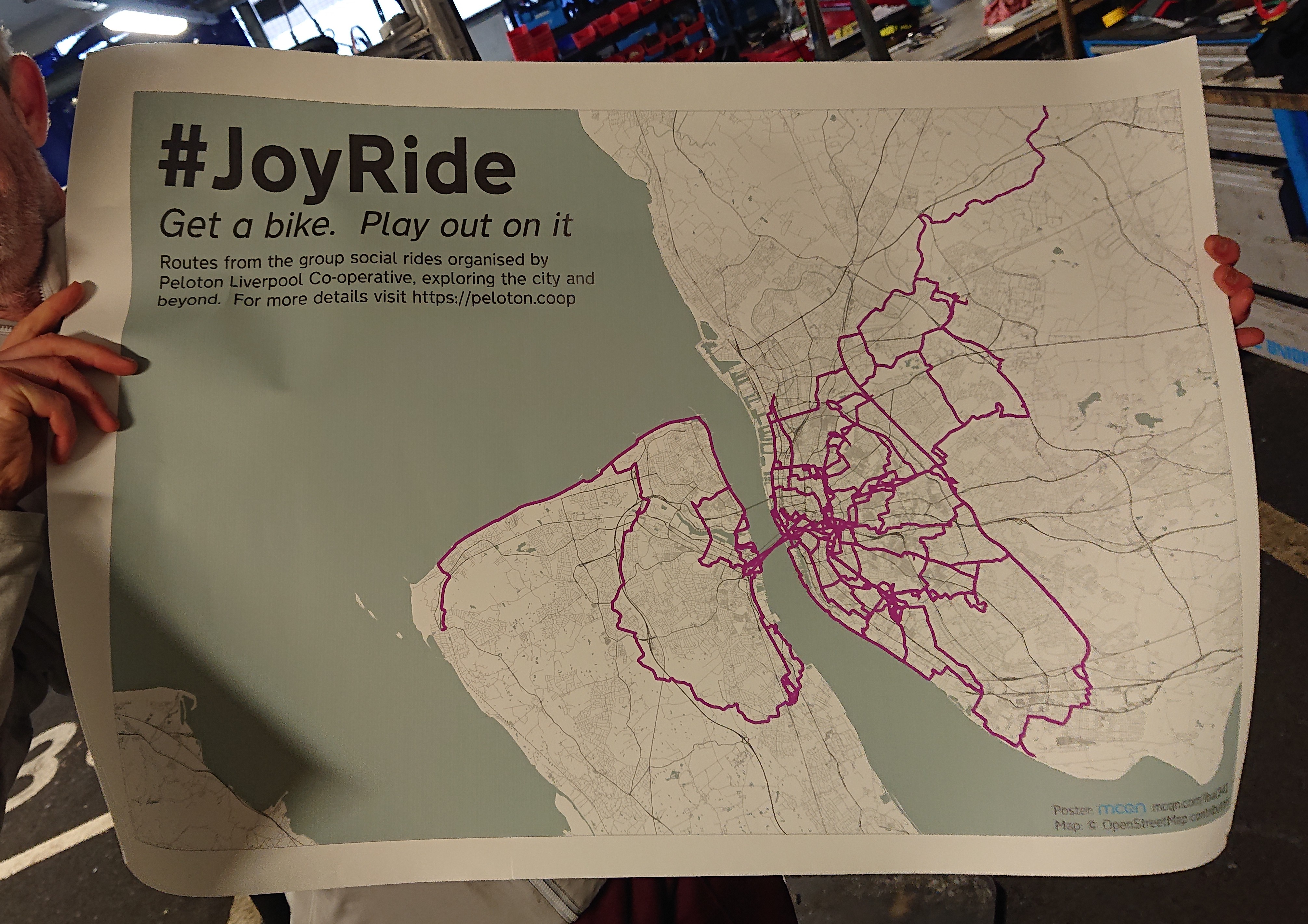
Pulling that together required a bunch of open-source tools, and he wrote up some production notes on the #JoyRide Poster catalogue page.
