The new school year is well underway, so I (Adrian) best get some weeknotes out while I can still shoehorn that metaphor into the title.
We’ve got five weeks to catch up on, so let’s run through the more interesting things as bullet-points; in no particular order:
- Neil has been making sure the Museum in a Box got plenty of love; with blog posts on both oral history and ways to share and remix your collections
- He also showed off our work at the DoES Liverpool Birthday Open Day
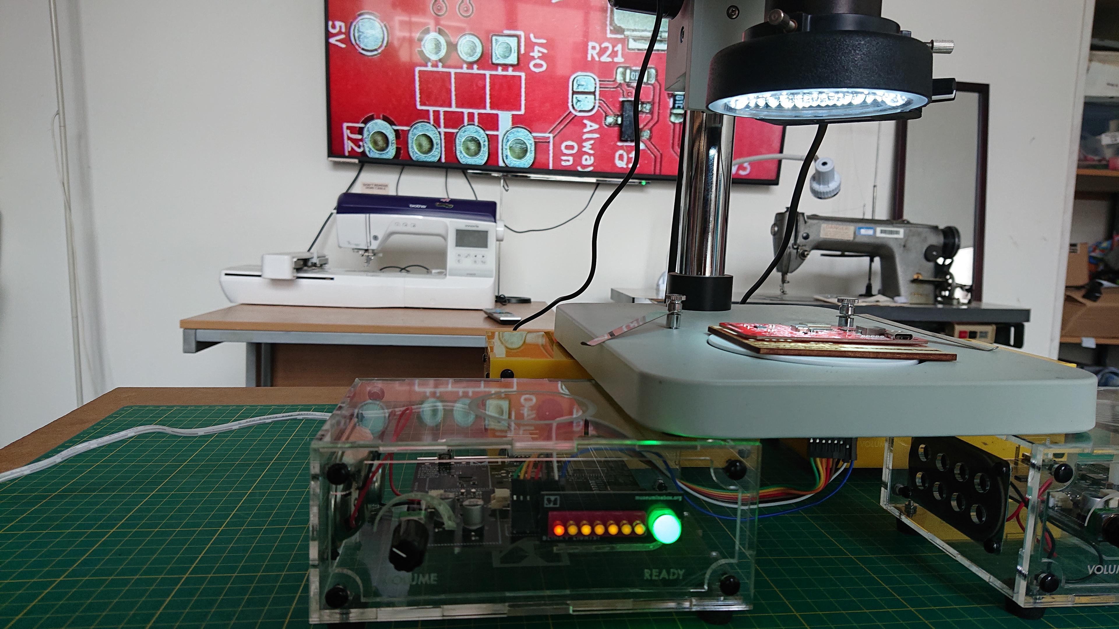
- After a comment over on LinkedIn, we knocked up a quick prototype to mash up a Museum in a Box with a microscope. We’ll be writing up a blog post on it, but here’s a sneak peek…
- Some of my blogging bandwidth, that could otherwise have gone into weeknotes, went into writing up our thoughts on sharing code and other design files
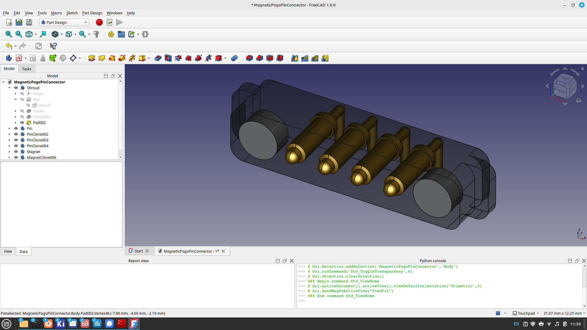
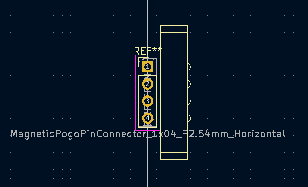
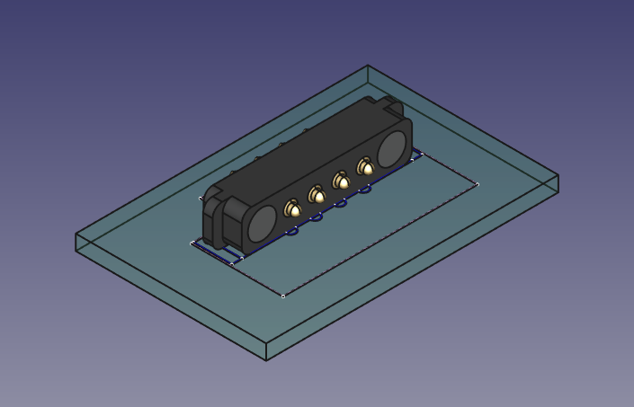
- I did get to do some FreeCAD and Kicad work. There’s a new project on the boil, and it will need some magnetic pogo-pin connectors. I found some good candidate parts, but needed to add them to Kicad so that I can lay out the PCB correctly. That took me into FreeCAD to design the 3D model; then Kicad to lay out the 2D footprint for the board; and back into FreeCAD with the Kicad-stepup workbench to bring the two together:
- And speaking of FreeCAD, I had a great chat with Jo Hinchliffe, to talk about the audio-level-shifter project; which he wrote up for the FreeCAD blog
- Finally, we’re getting towards the end of this batch of Museum in a Box and so we’re thinking about the next manufacturing run. The first step in that has been to order 1000 speakers.